Nand gate logic diagram and logic output youtube Circuit diagram using only nands Implementing any circuit using nand gate only
Logic NAND Gate Working Principle & Circuit Diagram
Gate nand nor logic circuits gates beginners electronic [diagram] and gate chip diagram Logic nand gate working principle & circuit diagram
Vhdl tutorial – 5: design, simulate and verify nand, nor, xor and xnor
Nand gate logic diagramCmos nand gate circuit diagram Nand gate circuit diagram and working explanationNand gate diagram.
Vhdl tutorial – 5: design, simulate and verify nand, nor, xor and xnorGate nand universal logic nor digital function into given made basic electrical other which below figure Implementing any circuit using nand gate onlyNand gate schematic diagram.

Circuit diagram of xnor gate using nand gates only
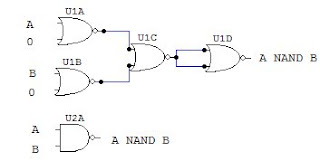
[diagram] circuit diagram nand gateCmos nor gate circuit diagram 2 input nand gate circuit diagramMy 2nd try finding the easiest way to compare two 8-bit buses. can you.
Introduction to logic gatesNand gate transistor diagram [diagram] circuit diagram nand gateNand boolean.

Transistor logic gates
Digital logic nand gate – universal gateElectronic circuits for beginners: logic gates Logic nand gate working principle & circuit diagramSolved: implement the circuit shown using nand and nor gates:.
What is nand gate and gateLogic nand gate working principle & circuit diagram Nand gate circuit diagramNand gates nor xnor circuit vhdl xor logic verify simulate circuits truth tutorial basic ckt.
Nand xor logic nor gates xnor circuit vhdl verify simulate input truth circuits tutorial engineersgarage scosche inverter inputs ckt combined
.
.


VHDL Tutorial – 5: Design, simulate and verify NAND, NOR, XOR and XNOR

My 2nd try finding the easiest way to compare two 8-bit buses. Can you

Nand Gate Logic Diagram And Logic Output Youtube
![[DIAGRAM] Circuit Diagram Nand Gate - MYDIAGRAM.ONLINE](https://i2.wp.com/www.researchgate.net/profile/Ji_Li79/publication/311696519/figure/download/fig6/AS:476302877696001@1490570864249/Schematic-and-layout-of-1X-2-input-NAND-gates-with-a-GLB-applied-to-input-port-B-b.png)
[DIAGRAM] Circuit Diagram Nand Gate - MYDIAGRAM.ONLINE
![[DIAGRAM] Circuit Diagram Nand Gate - MYDIAGRAM.ONLINE](https://i2.wp.com/circuitdigest.com/sites/default/files/circuitdiagram/NAND-Gate-Circuit-Diagram.gif)
[DIAGRAM] Circuit Diagram Nand Gate - MYDIAGRAM.ONLINE

Nand Gate Schematic Diagram - Wiring Flow Schema

Circuit Diagram Using Only Nands

2 Input Nand Gate Circuit Diagram